This post or let’s say series of post because the process will be split into different sections to make it easier to read.
Ok so now I have a design, but that’s pretty useless so how about we make it a reality.
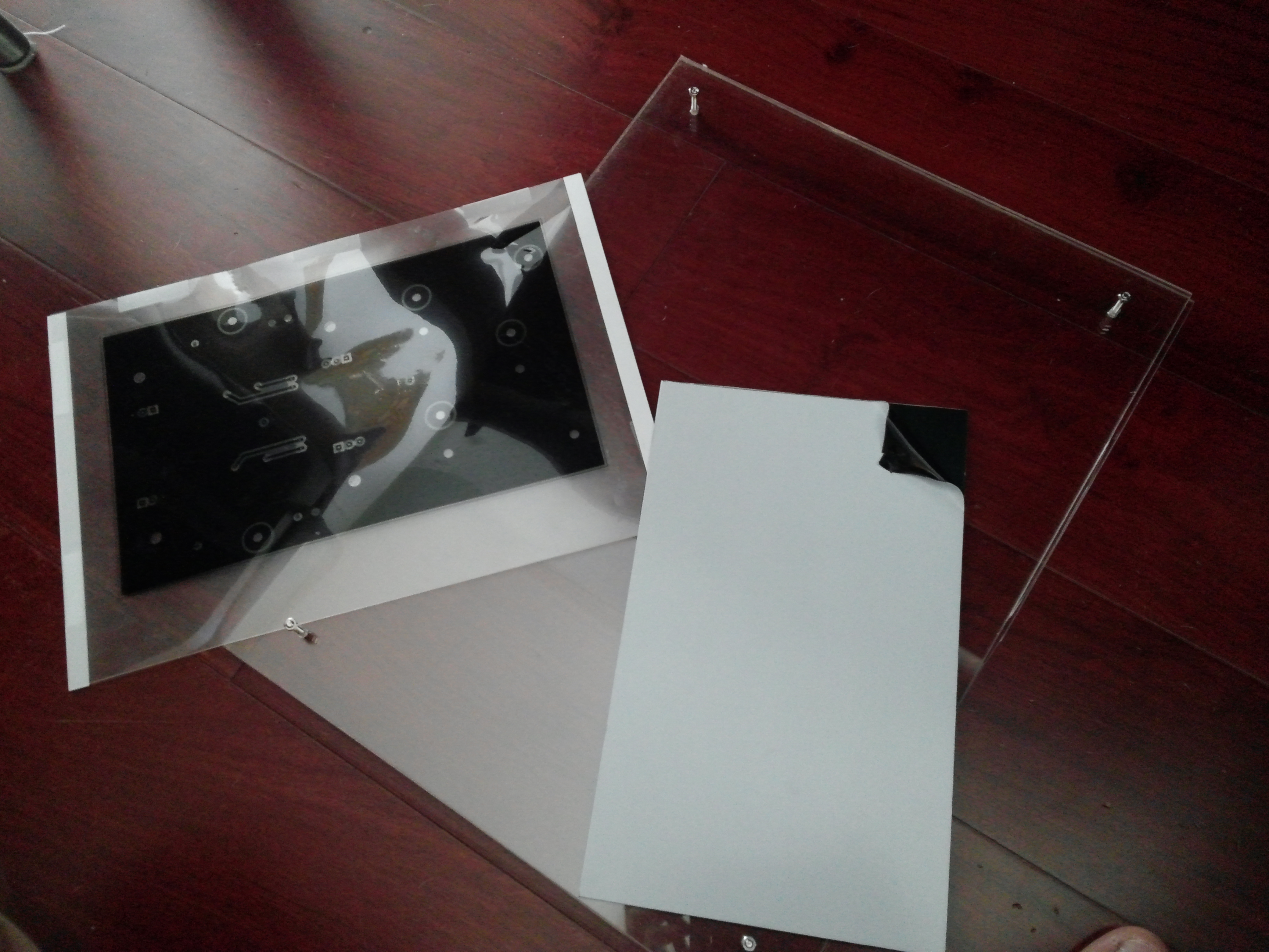
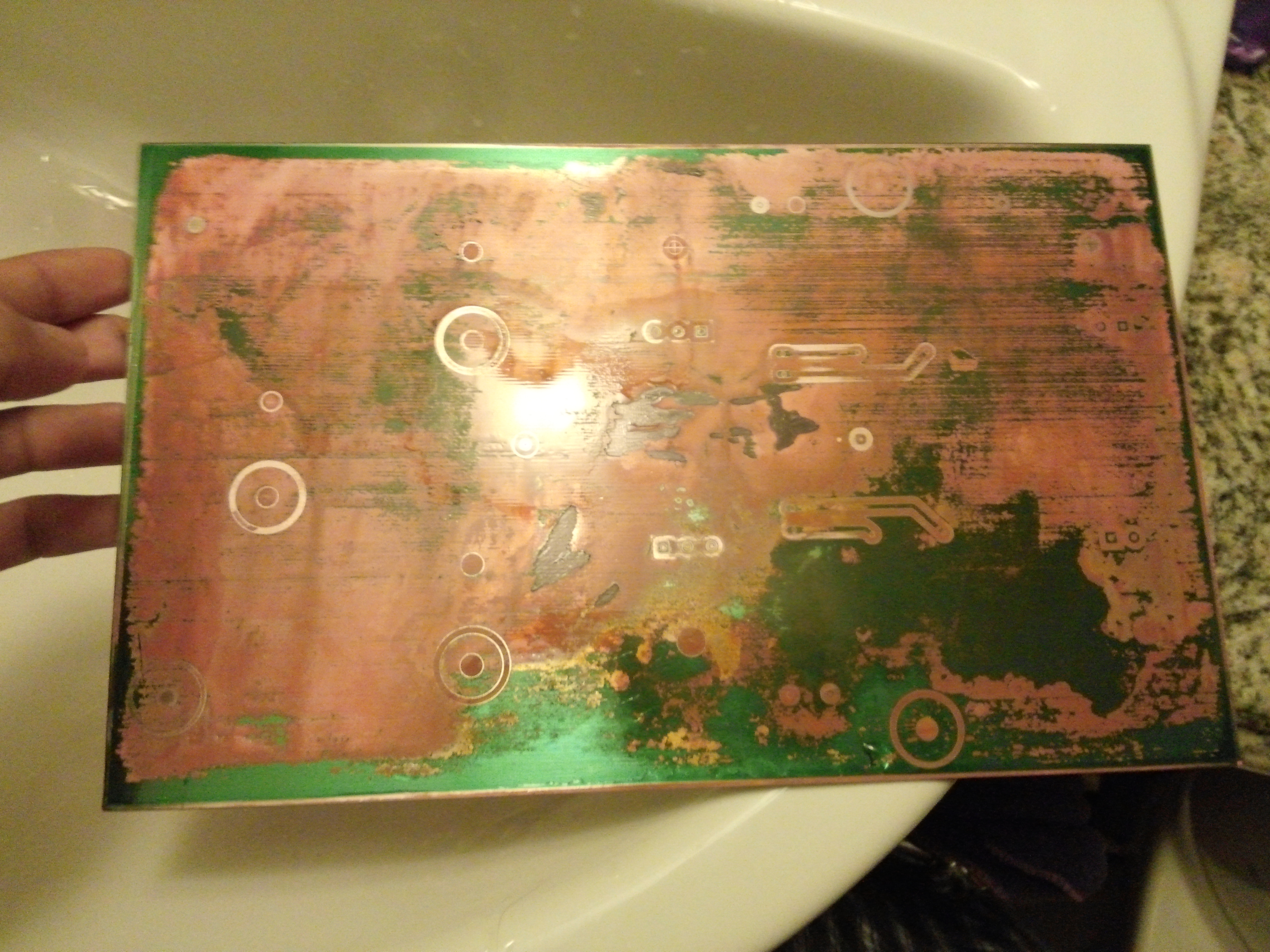
First of all, I needed a blank photoresist board and those didn’t come in the sizes I needed which was 150×244.12 mm, so I just bought some Kinsten presensitized PCBs from my local electronics shop ( Cost about 81 HKD, not to bad when compared to RSonline prices ). It was the perfect height so I didn’t need to cut it horizontally which saved me a lot of work, I just needed to cut it to length at 245 mm.
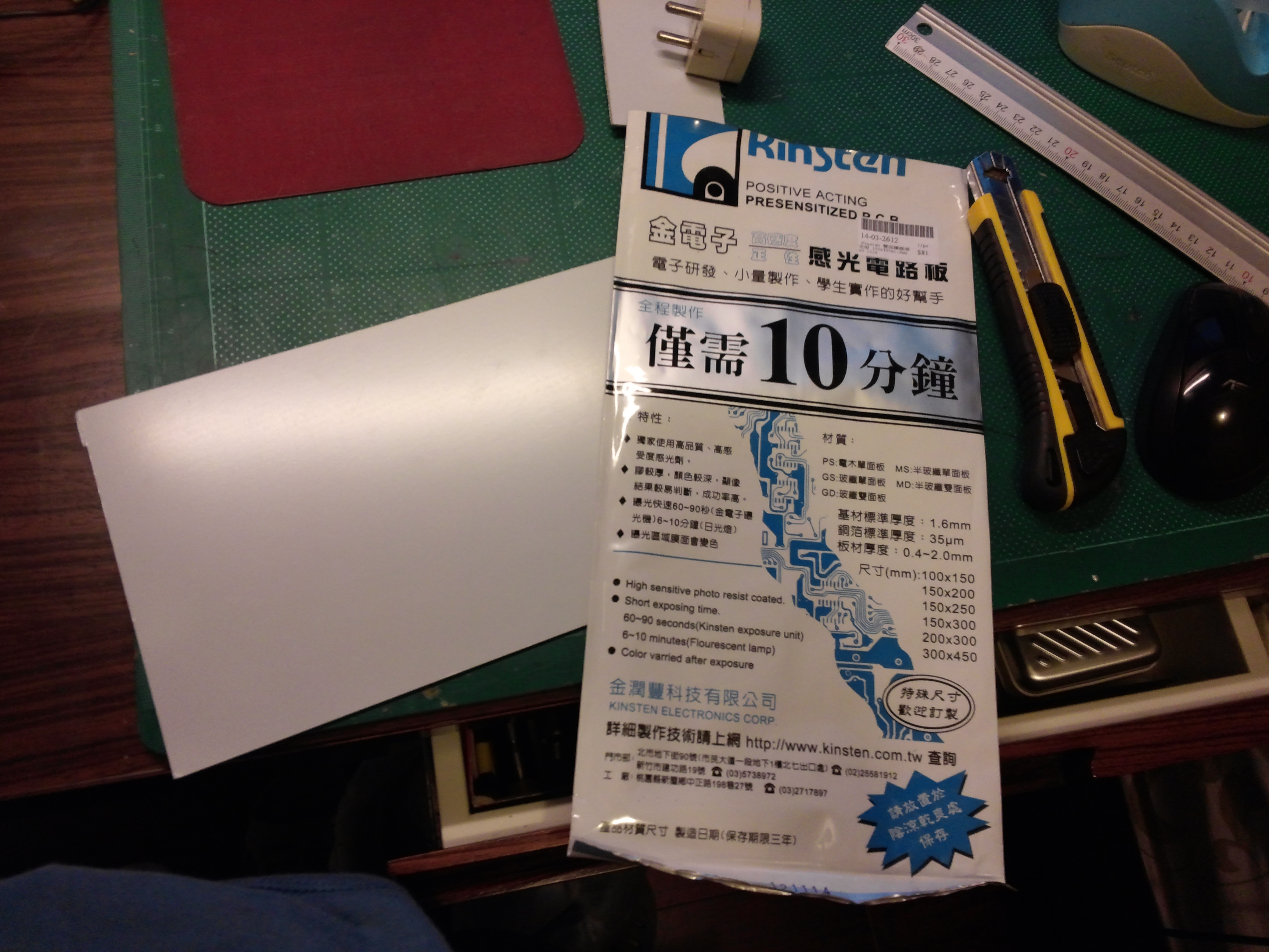
I cut it by scoring it with the yellow cutter you can see in the photo, I scored each side about 30-40 times then I snapped it which was quite easy to do, I filed the edges afterwards. The fiber glass eats blades like crazy so I prepared a few backups and of course when doing such work take care not to breathe in the glass fiber dust which is a serious carcinogenic meaning it can cause lung cancer if you experience prolonged exposure.
Well now the next step is to expose the board which I will be doing in my next post.
Part 2 is out! Read it here.