Usually getting the right exposure time for you PCBs(Printed Circuit Boards) is really hard, and I had a board fail on me recently because I switched my transparent medium( The thing I use to press the transparencies onto the blank PCB ) from a glass plate to acrylic sheets. Before, I found my exposure time just right ranging from 9-14 mins, but after using the same exposure time on acrylic sheet mediums the board came out as a disaster because the photo resist didn’t hold. Here is a picture of the failure:
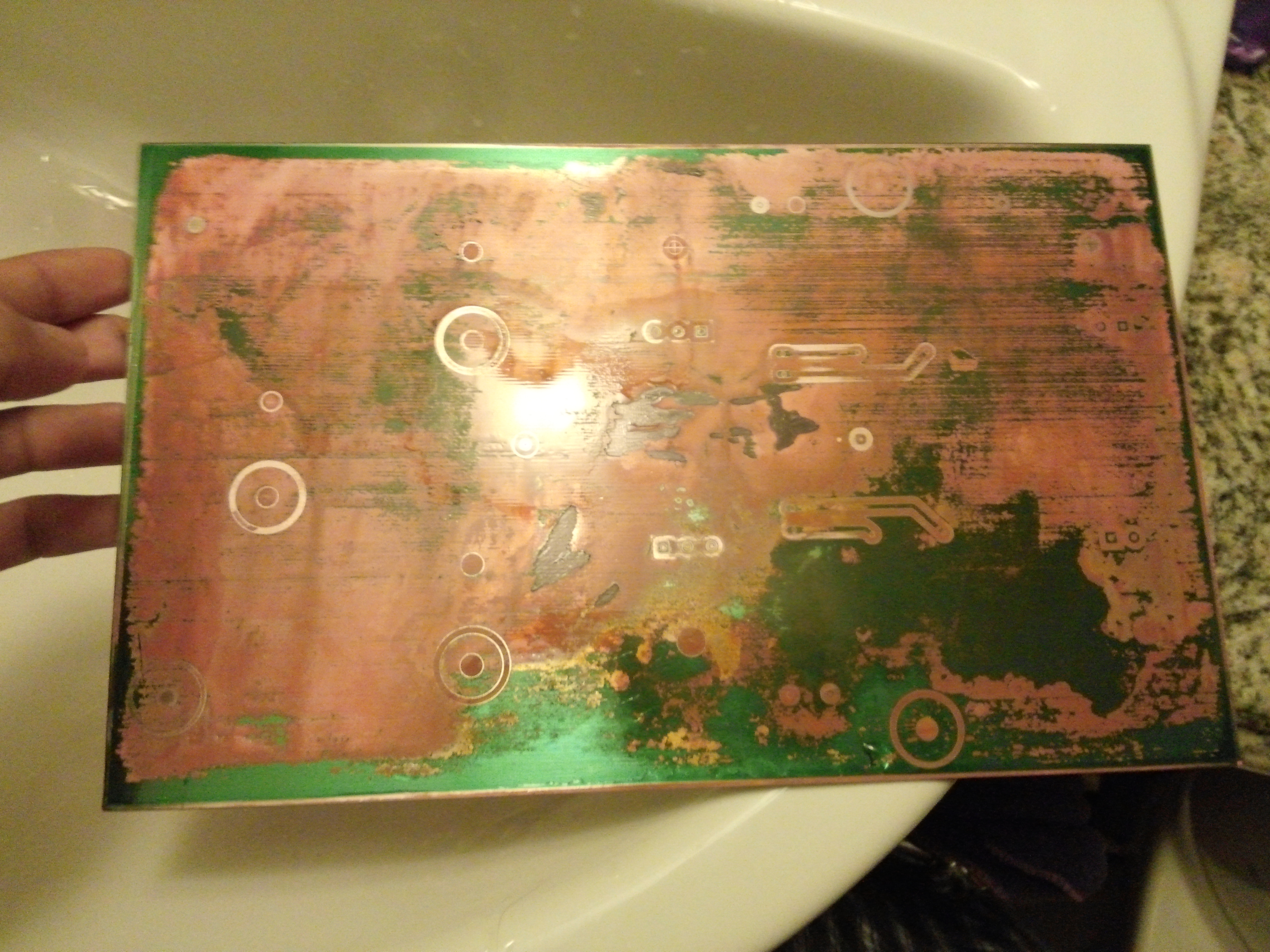
As you can see it really is bad so instead of guessing a time for the acrylic sheets I decided I would do this right so I made a simple dummy board for calibrating exposure time and also to check how small of traces I could make at which time interval.
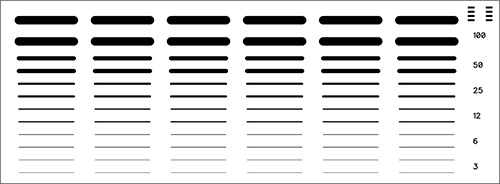
All you need to do is cover all of the “sections” only leaving one exposed, then after 1 time interval which in my case I used 1 minute, I uncovered another section. Rinse and repeat till all the sections are finished, I found my optimum time at 5 minutes. Beware even though the resist may look fine after developing there still may be a microscopic thin layer of resist still left. This happened at the 4 minute section where I first thought it was perfect only later to find out after etching that it didn’t etch so be careful about that.
Here is a PDF of the calibration board, just print it and get testing!