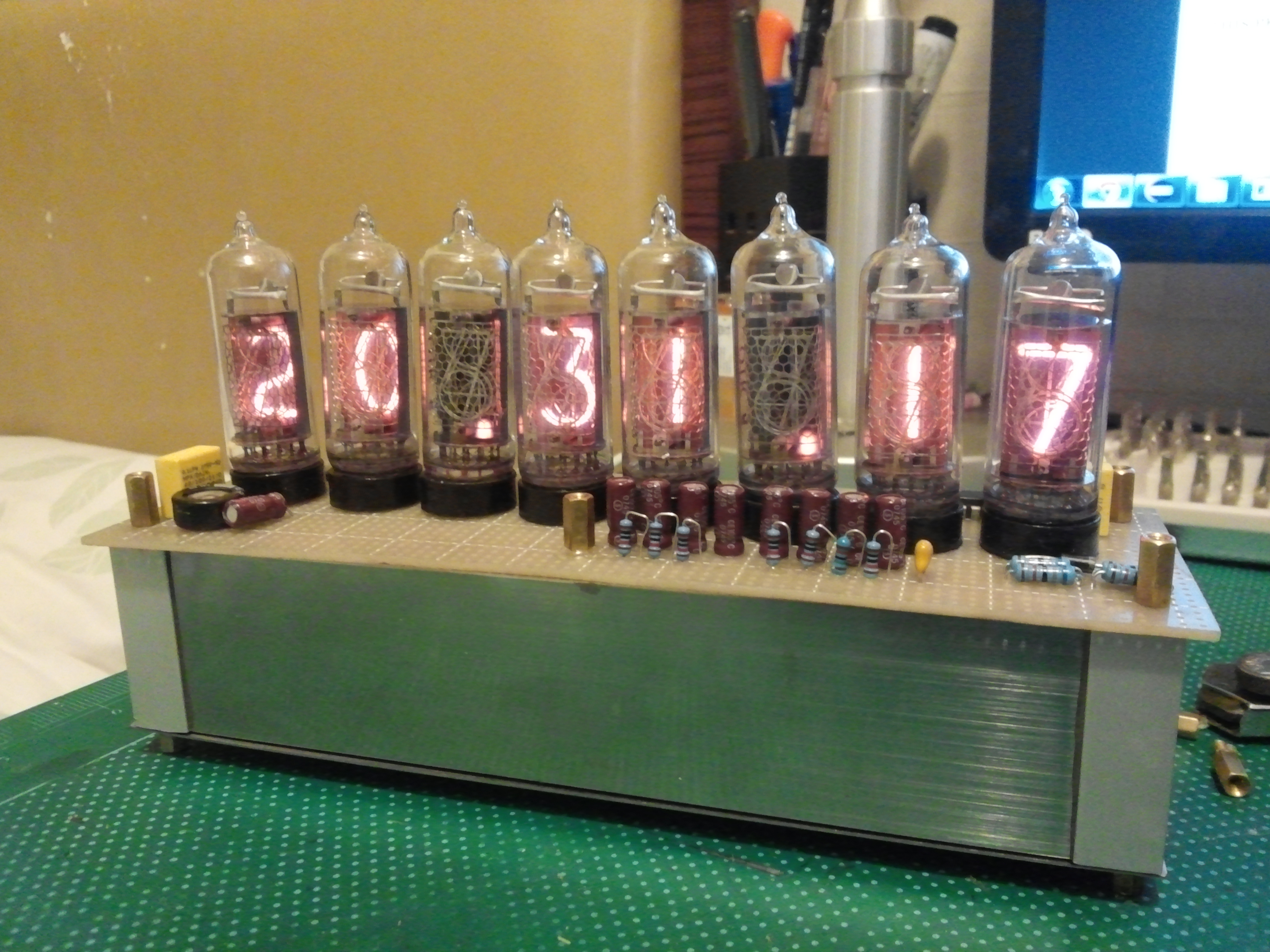
*Drum Rolls* *Cheers* YES it’s finally complete :’) THE DIVERGENCE METER IS COMPLETE !!! It took me a long time, it took me a lot of effort, it also caused me a lot of headaches but hey its complete!!!! Really awesome indeed, though I still have to tweak it a bit in the software, somehow release 0.1.0a of the software uses up a whopping 6KB out of 8KB of program space, I really hope to optimize the code and make the world line rolling much more visually accurate, otherwise it’s really awesome to look at especially at night 😀 the way nixie tubes display numbers gives that really special retro feeling yet it gives a futuristic feeling at the same time.
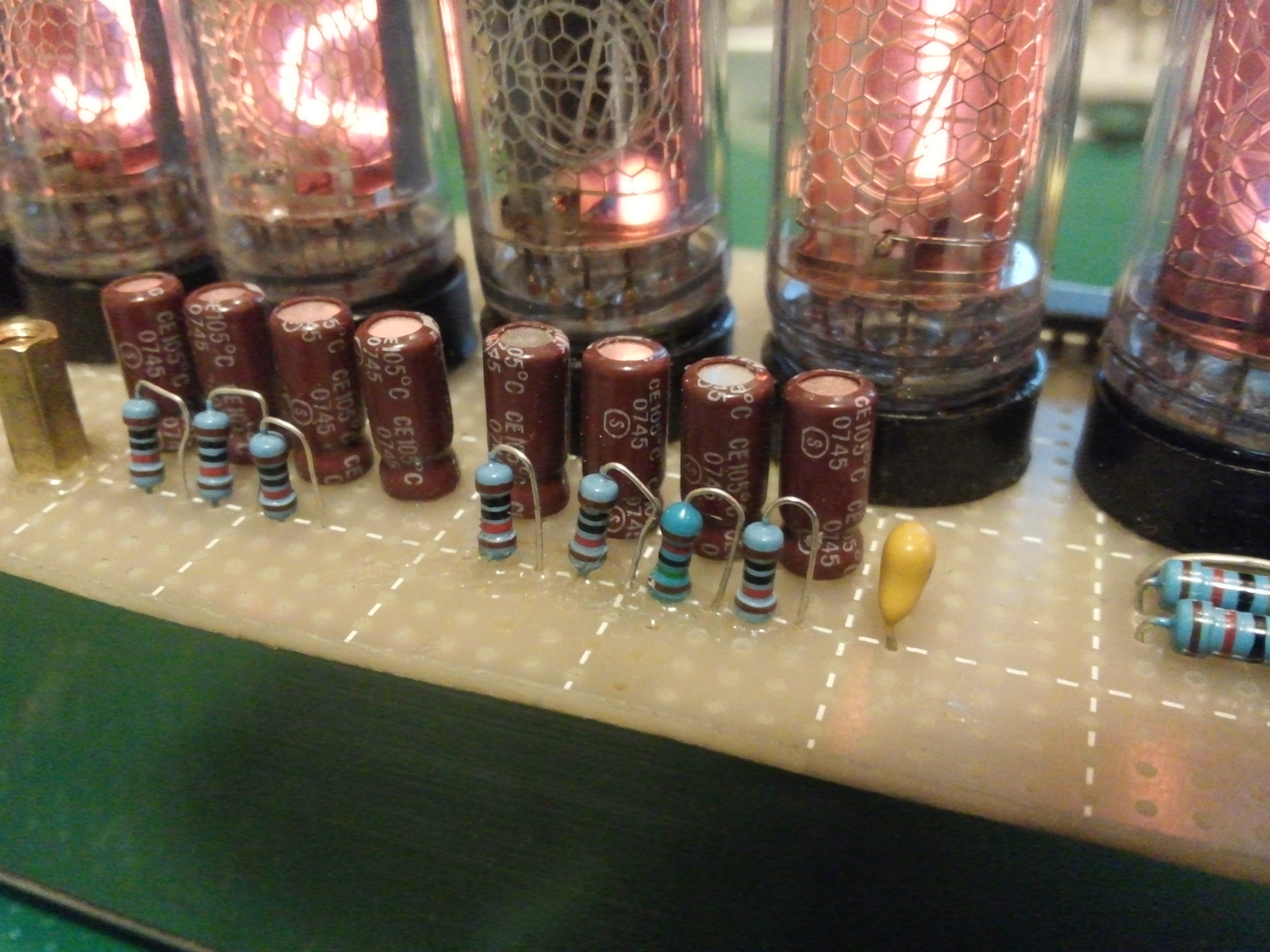
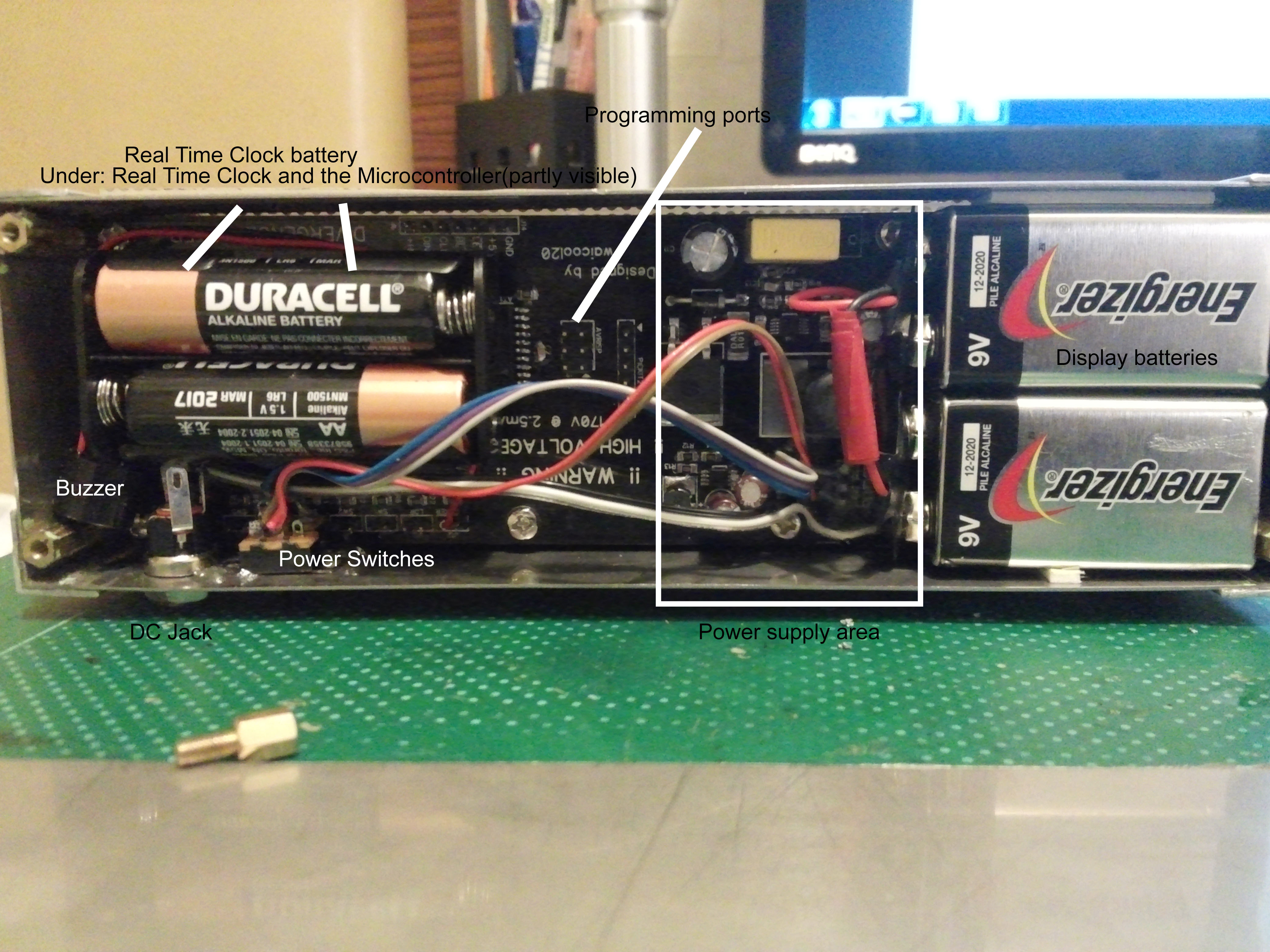
Now for some power consumption reports, well so far I’ve only had the thing on batteries with the longest duration of 2 hours but according to my estimations, measurements and fooling around(writing it down makes it science ;D ), I’ve found that it should run for around 4 hours on the lowest brightness settings and 11 hours on the highest. One thing I did though design in an “adaptive brightness” feature into the thing. Basically it uses an LDR (Light Dependent Resistor) and the device measures the environments brightness, when it’s dark it turns the display darker to save power and when it’s bright it turns up the display to make it easier to see.
Power consumption test data: https://github.com/waicool20/Divergence-Meter-Project/blob/master/Power%20Test.md
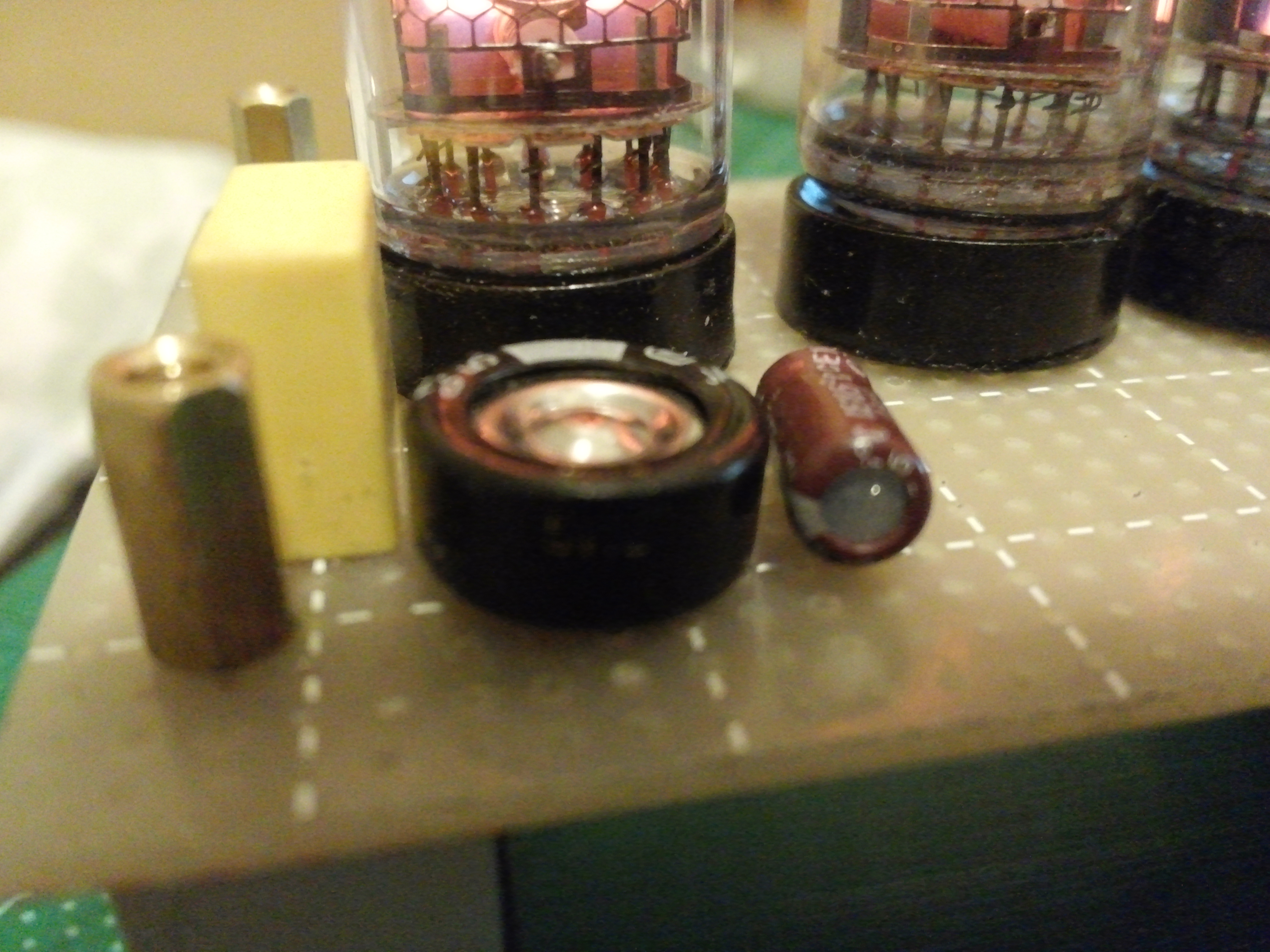
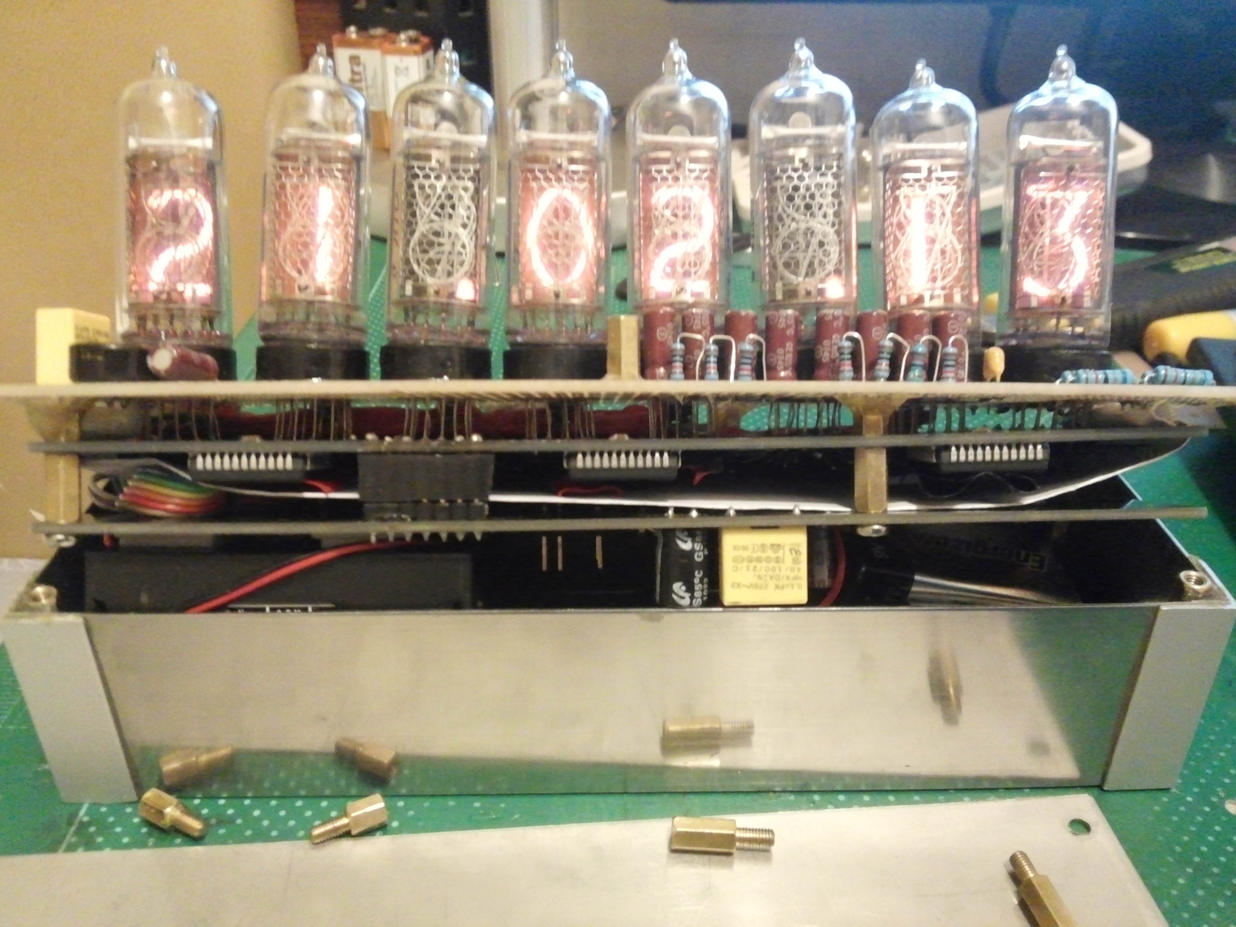
Also to note is that, even though I used NOS tubes (New Old Stock, basically new tubes that were never used for a long time therefore being “old”) I somehow still got cathode poisoning on one of my tubes D: well to fix that I just connected the HV pin to the tube anode directly and the cathode to a multimeter then the multimeter to ground. The measured current was around 5.5 mA and the digit was glowing really bright. IN-14 tubes are rated 2.5 mA max but driving them over-current is the only cure to cathode poisoning. After 10 minutes of baking the digit was displaying fine again and I have no issues whatsoever, not even the slightly darkened gloss that many people report. Though the tubes were quite warm after baking, but I guess that was to be expected.
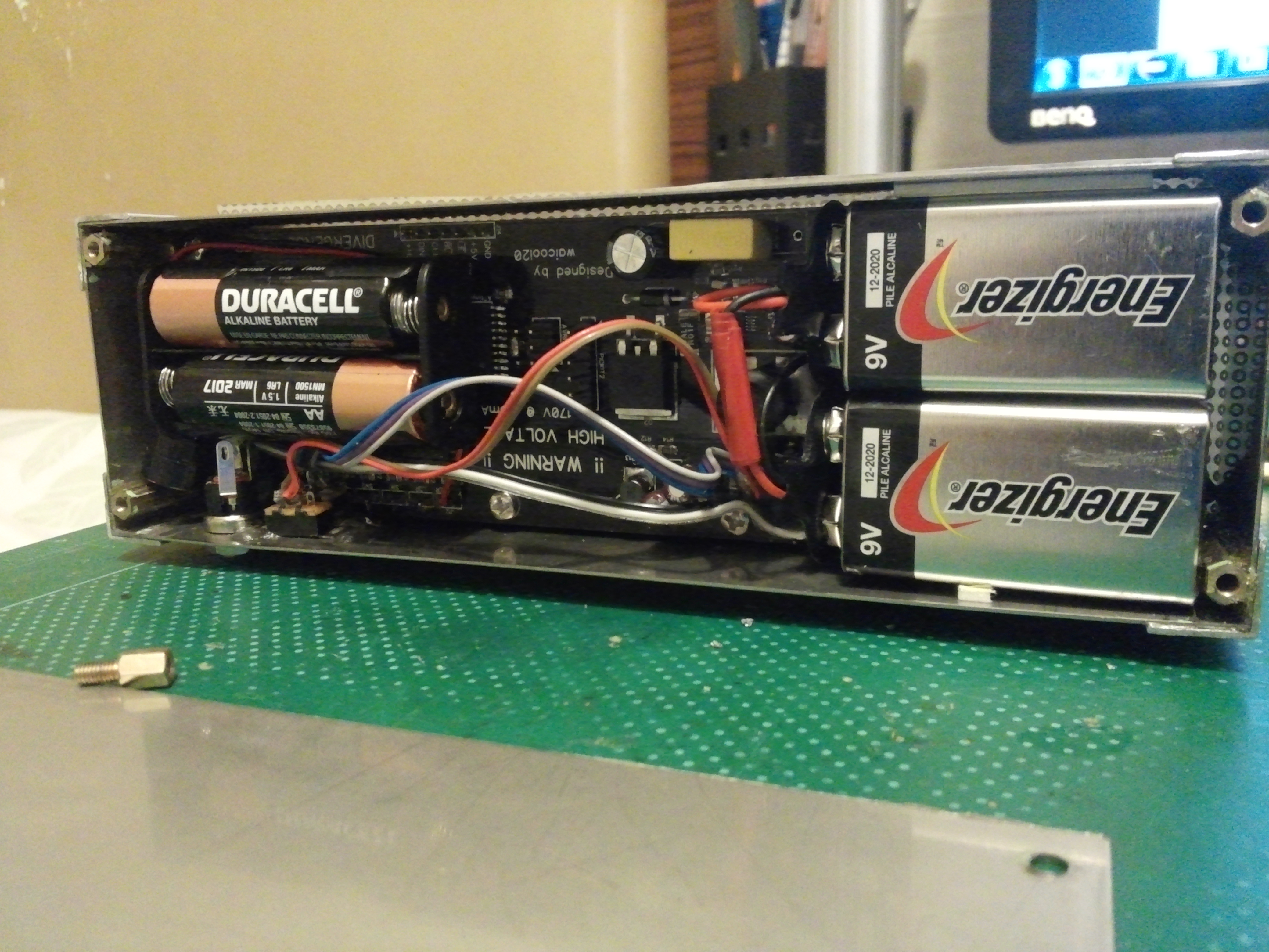
When making this thing, I used up a lot of epoxy first to secure the case together, and second to secure the wires to the PCB, I think that glueing the wires to the board is really important after soldering them especially the battery connectors, because when you’re changing the batteries it’s pretty certain that you will tug and pull on the wires and that can cause the joints to weaken/break. So to reduce the metal fatigue on the wires I recommend making a good solder joint then basically pour lots of epoxy to cover the wires to that they will never move again, but of course leave enough length so that it’s convenient for you to take out the batteries and such. Also to note, due to my “good design” when using a hex post on the main board, the post won’t leave enough clearance to put 2 batteries which is necessary for the device to operate. So it is a must that you use normal M3 screws, basically just go to a hardware shop and find a screw that fits into the posts and also one that is low enough that it doesn’t touch the terminals of the battery. Also when no battery is installed don’t worry about the thing getting shorted out since when your using the DC jack its basically disconnected. Also don’t worry about short circuiting the board, the power supply chips have a short circuit protection feature built in, but in the end it’s best not to let it happen.
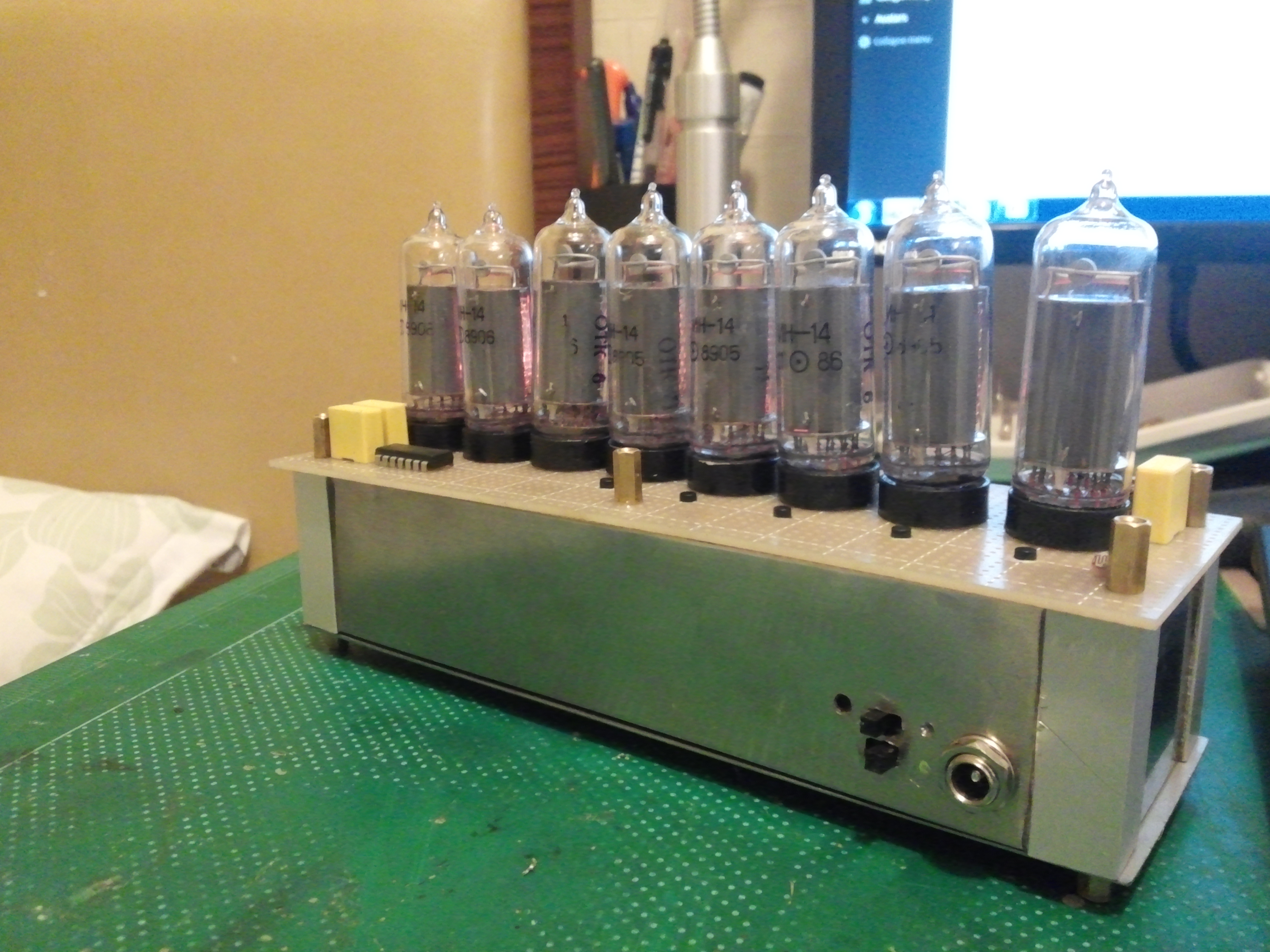
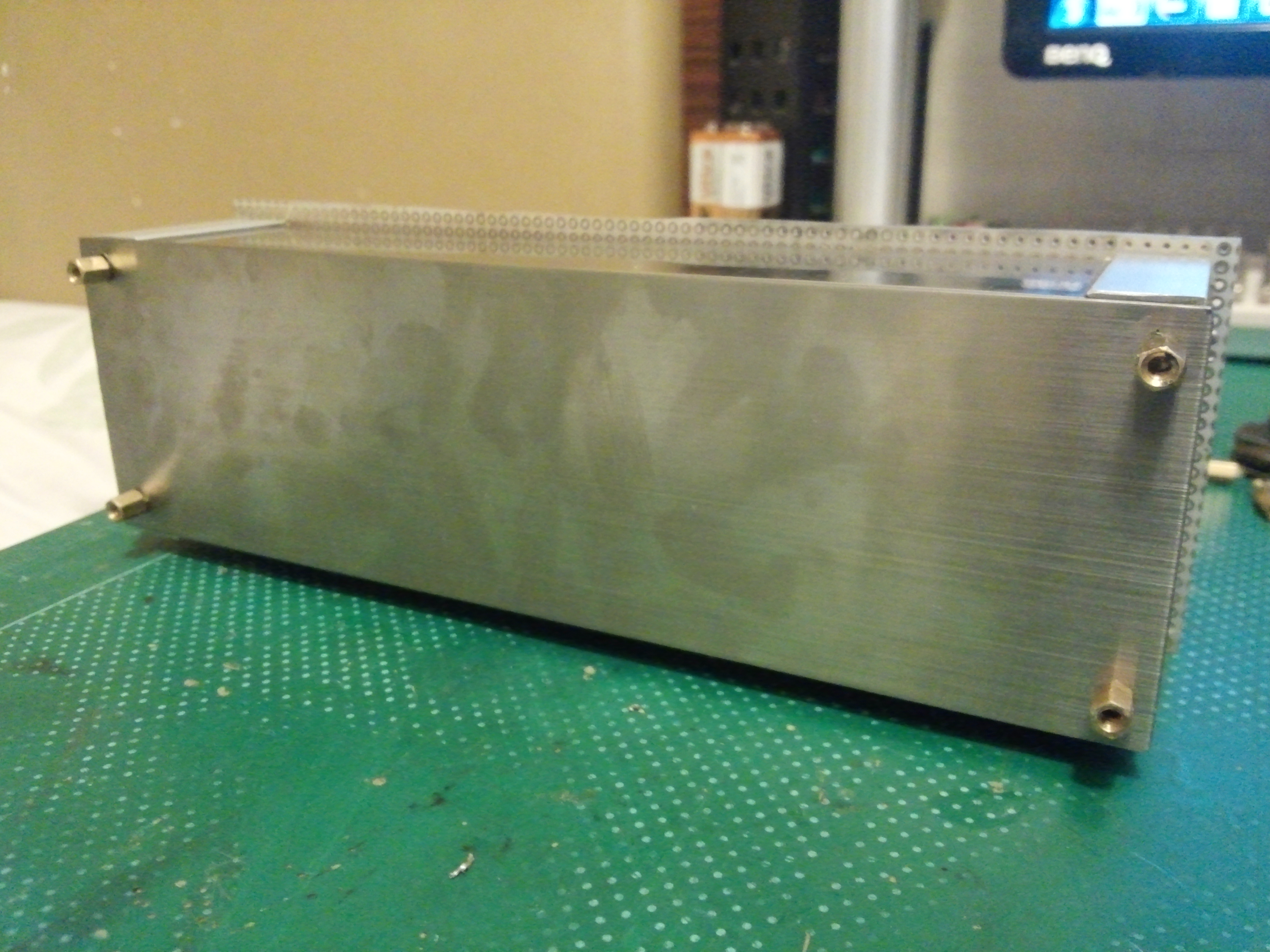
The case…. well it was somewhat bigger than expected but that was due to that accuracy of the guys at the steel workshop, and well I don’t really mind having a somewhat “fat” meter. And well ….it is freaking hard to drill through steel especially when your drill bits are dull so buy some new ones and drill slowly! Or else you will end up with an ugly case like mine orz I kinda messed up with the holes near the switch…but oh well I’ll probably replace this case sooner or later in the future.
One final thing before I put up some photos is that this project is Open Source and Open Hardware, you’re welcome to modify the files/code to your liking, you can even distribute them all you like. Just make sure you follow the rules of the Licenses. The software is licensed under GPLv3 and the hardware is licensed under the TAPR OHL, so go look those up. Btw I have some leftover PCBs, in fact 9 pairs of the design, I’d gladly sell em(40 USD a pair) to you if you want *shameless advertisement* :p just email me at [email protected] or [email protected]
Here is a full list of things that I can provide.
Project files: https://github.com/waicool20/Divergence-Meter-Project
Your welcome to create an issue to request features or create a pull request to suggest changes 😀 let us keep up with the open source open hardware spirit 😀
I will most likely write up a user manual of some sort later in the future when I’m free so that you guys can learn how to use the device after making one yourself 😀 or you can just code up your own firmware ~~ whatever El Psy Congroo!!
Pictures:
Last but not least: A video of the divergence meter rolling a world line 😀 Can you recognize which world lines those are *smirk*
And to quote my words within my project files:
Safety Disclaimer
THIS PROJECT CONTAINS HIGH VOLTAGES (~170V) IT CAN KILL YOU IN THE WORST CASE SO BE CAREFUL.
The project has already minimized High Voltage (assuming you have a solder mask) so the only places you need to be careful are the parts around the LM3481, the HV pin on the board connector, and most of the pins on the Nixie Board. When constructing the device, please make sure no high voltage areas touch the case or anything that’s not supposed to be “live” like seriously it will make your life easier.
When handling this device be aware that high voltage can still exist even when the device is completely powered off because of residual power in the capacitors, wait at least 3-5 seconds before touching anything on the pcb after unplugging the device.
Well you are at your own risk when you attempt this project, you can’t hold me liable for anything that happens to you, your property or anybody/thing affected by your actions.
Do you want to meet me and my meter!? Well I’ll be attending ACGHK 2015 (anyone from HK!?!?) this coming sunday! I’ll probably be the only one with a divergence meter(and a lab coat) so come find me 😀
Oh well have a nice day!
El Psy Congroo,
waicool20
Want to read more? Here’s the Last Update!